Objective for URS of Lifting & Tipping Device:
This document is generating for the purpose of specifying the URS of Lifting & Tipping Device . The User Requirements Specification (URS) is provided to define the important components, variables and options necessary for the Supplier to provide a functional of multi-mill machine that meets the needs in the most cost-effective method possible. The URS of Lifting & Tipping Device is also provided to the Supplier to provide a price quote for the supply for multi-mill machine including the design, Performance and manufacture of the equipment.
The device shall be interfaced to the output and located in a designated operating area.
Table of Content for URS of Lifting & Tipping Device
| Description |
| Objective |
| Table of contents |
| Approval of Documents |
| Scope |
| Location of equipment |
| Communication |
| Applicable codes and standard |
| System/equipment/instruments details |
| Scope of supply |
| Brief system description |
| Technical specification |
| Safety features |
| List of Abbreviations |
Approval of Documents:
Prepared by:-
| Name | Designation/Department | Signature | Date |
| Executive/ QA |
Reviewed by:-
| Name | Designation/Department | Signature | Date |
| Manager/Production | |||
| Manager/Engineering |
Approved by:-
| Name | Designation/Department | Signature | Date |
| Manager/QA |
Scope:
- The scope of this document is to define the requirements of the Lifting and tipping device in facility.
Location of equipment:
- Machine will be installed in the granulation area as well as compression area with Class D area cleanliness.
References
- Reference has been taken from the existing equipment in the facility and from internet or vendor brochure.
System/equipment/Instruments details:
| Name of the equipment | Lifting and tipping device |
| Capacity | As per requirement |
| Model/Type | As per cGMP model |
Scope of Supply:
| Type of Device | Lifting and tipping device |
| Machine Standard | The current state of the art GMP Compliance. European medicine agency (EMA) and WHO Regulations compliance. |
| Machine design standard for safety | ISO 13852:1996 safety of machinery -safety distance to prevent danger zones being reached by upper limbs.ISO 13853:1996 safety of machinery safety distance to prevent danger zones being reached by lower limbsISO 13854:1996 safety of machinery- minimum gaps to avoid crushing of parts of the human body.ISO 14110:1998 safety of machinery- interlocking device associated with guards- principles for design & selection. |
| Room Condition | Room Temperature: – NMT 25 degree Celsius.Relative humidity: – NMT 55 %Zoning: Class D GradePressure:15 Pa |
| Features | Design conforming to cGMP standardsContact part SS 316 and noncontact parts SS 304.Simple and Convenient operation, Changeover, Cleanliness, Operator protection and Ease to maintenance.Easy cleaning designed with easy removal weight adjustment sector.AC Frequency drive for motor |
| Document & Certificate | Manuals and Maintenance Instructions Operator manualInstallation and assembly instructions for all devices.User’s manuals for all components.Trouble shooting guide.Maintenance Manual.Safety instruction.Training documentation. Electrical and Control diagrams Single line drawing for electrical distribution.Circuit diagramsCable list.Equipment location drawing for electrical equipment and instruments. |
| Qualification Protocols | DQ Protocols and reports.FAT protocol and report.SAT protocol and reportIQ protocol and reportOQ Protocol and reportVendor should organize for Execution of IQ/OQ and support for PQ |
| Training | Vendor should impart necessary Operational training to user department and maintenance training to maintenance department. |
| Test ,Calibration, MOC Certification | All test certificate for brought items will be provides during FAT with FAT DocumentsMOC Certificate will be providing during FAT with FAT documentsCalibration certificate provide for gauge during FAT. |
Brief system description for URS of Lifting & Tipping Device:
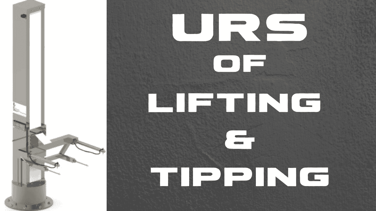
Tippler-Lifting and tipping device is a hydraulic device which is having an arm used for lifting and turning FBD bowl by 180 degree. It is used to unload FBD bowl material in to Cone mill or Multi mill or Oscillating granulator in a dust free way for downsizing or dry milling. The operation is completely dust free and eliminates manual handling or scooping.
The FBD Bowl is placed beneath the Tipper & inverted cone of the Tipper is lowered so that the brim flange of the bowl touches the inverted cone. Both are clamped together with quick fixing clamps. The whole assembly is raised.
The basic construction of the machine consists of :
- The equipment is designed with cylindrical body and tapered bottom with a large sized lid for easy cleaning process. They are made from stainless steel material such as SS 316 Non contact parts SS304 with matt finish
- Non metallic contact parts SS304 with matt finish, any material with food grade quality having no potential impact on the products
The Drive:
Equipped with frequency controlled drive. Large torque can be achieved even at low speed and because of its high regulating speed it is centrally driven by an electric motor
Bin
Shell-The shell consist of a square central part with conical frustums at one ends. This cone is provided with a butterfly valve used for discharge a powder. Top is square in shape and has a welded lid (manhole) from the top. The manhole is provided with a air tight cover & Gasket. Discharge- A manually operated butterfly valve is provided at the bottom for discharge. Mounting – The bin is provided with independent trolley to facilitate the bin loading and unloading in the arm.
Lifting Device:
Two ‘C’ frame structures are used to build a column. Column frame is connected with each other by top & bottom Plate. The column is then connected at the base on a revolving circle mounted on a thrust bearing. The circle is connected on the base plate. A hydraulic cylinder is mounted inside the column to support inside carrage, connected by chain and sprocket assy Inside carriage is connected to outside carriage & outside carriage holds the bin arm.
Lifting Arrangement- A system mounted on the hydraulic cylinder head lift the bin arm with a heavy designed carriage. The bin arm is mounted on a box inside the column which is guided by the bearing in a channel on two opposite sides inside the column.
Power pack- An MS powder coated tank act as the oil reservoir and also support the hydraulic circuit. The hydraulic power pack unit consists of a single gear pump coupled to flange mounted 3 phase electric motor suitable capacity with suitable bell housing and gear coupling.
The pressure is controlled by 2 relief valves. Two relief valve controls the high maximum allowable pressure and return pressure of pump. Both relief valves shall be direct operated. A pilot operated check valve is provided to lock the pressure in the cylinder so that it will not come down when not desired.
A solenoid operated direction control valve controls the cylinder movements upwards as well as downwards This is operated by a press down push button. Y piece. A “Y” shape connection is made to discharge the material in two charging ports of the compression machine
Platform:
A sturdy platform is made and installed on the machine, to allow the y piece & the IPC bin to rest on it
Electrical chamber and mechanical chamber:
All mechanical components such as gears, motors, and moving belts, as well as electrical components such as wiring, switches, and MCBs, are installed in this segment.
Technical Specification for URS of Lifting & Tipping Device:
| Particulars | Specification |
| Model/Type | As per cGMP model |
| Machine weight | As per requirement |
| Capacity | As per requirement |
| VFD | As per motor rating |
| Overall dimension (mm) | As per requirement |
| Lifting unit | Hydraulic cylinder as per machine requirement |
| Contact parts | Shell, ConeTop valvesLidTC |
| Non Contact exposed parts | Clamps Trolley Bin holding arms Column covers Base plate Covers, Break paddle and assy |
| Non Contact Internal Parts | Column Base plate Inside carriage sprocket chain Trolley |
| Machine Mounting | It should be on Anti vibration pad with 100 mm distance piece. |
| Electric panel | Electrical panel with push button and digital indicator.Emergency Switch.On/ off switchHMI Electric panel with MCB, contactor, overload relay, controls relay, VFD, SMPS. |
| Identification | Details of Make, Name, Serial. No., Capacity, Model and Year of manufacture should be available |
Safety Features:
| Critical Variables | Acceptance Criteria | Reference |
| MCB | MCB is provided so that when there is an overload in current or any short circuit then the MCB trips. | Safety Requirement |
| Mechanical Guard | Mechanical guard for all rotating parts. | Safety Requirement |
| Joints | Welding of joints without any welding burrs. | Safety Requirement |
| Metal Parts | All the metal parts should be properly grounded without any sharp Edges. | Safety Requirement |
| Leveling and Balancing | Equipment should be properly balanced & leveled. | Safety Requirement |
| Installation | All the Installation must be in accordance with the cGMP. | Safety Requirement |
| Electrical Wiring And Earthing | Electrical wiring should be as per approved drawings. Double external Earthing to control machine (panel and motors) and operator should be provided. | Safety Requirement |
| Noise Level | NMT 80 db. | Safety Requirement |
| Emergency/Safety Switch | Provided easy access position | Safety Requirement |