Objective for PQ for Dynamic Pass Box
To determine that the PQ for Dynamic Pass Box perform as intended by repeatedly running the system on its intended schedules and recording all relevant information and data. Results must demonstrate that it consistently meets pre-determined specifications under normal condition, and where appropriate the worst-case situations.
To verify that the equipment operates in accordance with the design and user requirements as defined by set Acceptance Criteria and complies with relevant cGMP Requirements.
To verify the Performance features of Dynamic pass box and to ensure that it produces desired Quality & rated output according to manufactures specifications.
To verify all the performance features from user point of view of the Equipment
TABLE OF CONTENT
| PARTICULARS | PAGE NO. |
| Title page | |
| Table of content | |
| Objective | |
| Scope | |
| Qualification Schedule | |
| Location of Equipment | |
| Validation Team and Responsibility | |
| Pre-approval of documents | |
| Scope of supply | |
| Brief process description | |
| Performance qualification procedure | |
| Performance verification | |
| Performance qualification report | |
| References | |
| Result | |
| Deviation/change control | |
| Summary | |
| Conclusion | |
| Recommendations | |
| Attachments | |
| Post approvals |
SCOPE
The scope of this Performance qualification protocol is limited to qualification of Dynamic pass box installed in Packing Material Sampling Area.
This Protocol will define the methods and documentation used to perform PQ activity the Dynamic pass box for OQ. Successful completion of this Protocol will verify that Reverse Laminar Air Flow meet all acceptance criteria & ready for daily activities
This document is applicable for Dynamic pass box located at company
QUALIFICATION SCHEDULE
Frequency
Performance check of the machine should be re-qualified after every 5years ±2 months.
LOCATION OF EQUIPMENT
The location of the equipment is in between Material Receiving area & sampling area at factory.
| S. No. | Name of Equipment | ID No. | Room Name | Section |
| 1 | Dynamic Pass Box |
VALIDATION TEAM AND RESPONSIBILITY of PQ for Dynamic Pass Box
| Department | Responsibility |
| Engineering | Preparation of protocol and compilation of report. Review of protocol and report. Execution of Qualification activities with the user/ concern departments per the protocol. Responsible for the compliance of qualification data |
| Warehouse | Review of protocol and report. Execution of qualification activities as per the protocol |
| Quality Control | Review of protocol and report. Execution of qualification activities as per the protocol |
| Production | Review of protocol and report. |
| Quality Assurance | Review, approval and certification of the protocol / reports. Execution & approved of qualification activities as per the protocol& certification after successful qualification of equipment. Responsible for the compliance of qualification data |
PRE APPROVAL OF DOCUMENTS
Prepared by
| Designation | Name | Date | Signature |
| Executive/Officer Engineering |
Checked By
| Designation | Name | Date | Signature |
| Head Engineering | |||
| Head Warehouse | |||
| Head Quality Control | |||
| Head Production |
Approved by
| Designation | Name | Date | Signature |
| Head QA |
Scope Of Supply:
| Description | Specification |
| Make | |
| Model | |
| Serial No. | |
| Control system | 230 volts, Single phase power supply |
Brief Process Description:
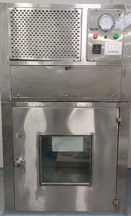
Dynamic pass box is normally used to transfer materials and goods between clean rooms of different levels or between clean room and non-clean room. Besides UV light and an interlock system, dynamic pass box is equipped with a suction HEPA filter. A dynamic pass box works like an airlock or laminar it has an interlocking system on both sides to protect from contamination and cross-contamination. Dynamic pass box door can open one side at once, and the other side door remains closed.
Dynamic pass box is a self-cleaning pass box. The air sucked by a centrifugal blower than passed through HEPA filter. After the pressure is equalized, the filtered air enters the working zone at a uniform air velocity, forming a clean working environment
When the material is put inside pass box & the door is closed, UV light will turn on and material is placed under UV for some time to kill bacteria. Then the material can be taken out
PROCEDURE of PQ for Dynamic Pass Box
- The Performance Qualification status of the instrument was checked and the execution was started only after completion of operational qualification report.
- Availability of calibration certificates of all the attached instruments shall be checked.
- The power supply and connected utility shall be checked before starting Performance Qualification.
- The operating functions of control panel switches and buttons shall be checked.
- The motor functioning test shall be performed.
- No Deviation should be observed during Performance Qualification.
PERFORMANCE VERIFICATION
Objective of this performance verification is to provide documented evidence that equipment performs as per respective and up to its operating & performance range
- Standard Operating Parameters Verification
To verify the standards operating procedure required in the qualification of Dynamic Pass boxshall be of current version.
| Sr. no. | SOP title |
| 1. | SOP for operation & cleaning of Dynamic Pass Box |
| 2. | Calibration of Instruments |
| 3. | Preventive Maintenance program for all Machines &Equipment’s |
| 4. | HVAC Validation and Re-Validation |
Calibration of all measuring Instruments
Verify the calibration of all the measuring instruments used during qualification of Dynamic Pass box, as mentioned below.
| Sr. No. | Item Description |
| 01. | Anemometer |
| 02. | Particle count |
| 03. | Aerosol Photometer |
Observations & Results
Ensure calibration of the instruments used to test validation parameters during qualification of Dynamic Pass box are in valid period& record the calibration details
| Sr. No. | Instrument Name | ID no. | Calibrated on | Calibration due on | Calibration report No. |
Checked By (Sign & Date): __________________
PROCEDURE FOR AIR VELOCITY MEASUREMENT
Ensure that the Supply blower of the Equipment containing HEPA filter is “ON” prior to the start of the observations
Ensure that the instrument (vane or hot wire anemometer or flow hood with flow meter) is having a valid calibration certificate.
Measure the air velocity (FPM) at five different locations of the supply air grill at a distance of about 150mm (6”) as shown below:
The measuring time at each location should be at least 10 seconds and average reading should be taken
Record the reading in the raw data format of external agency and attach the same
Calculate the average velocity of the air coming from Supply Grill as per the following formula Average air velocity (FPM) = Readings of (A + B + C + D + E) 5
Acceptance Criteria:
- Average measured clean air cross sectional velocity under the absolute terminal/filter module should be 70- 110 FPM and /or more depending upon the filter size. Filter area and / or rated velocity across the filter, when measured about 6 inches downstream of the subjected filters.
PROCEDURE FOR MONITORING THE NON-VIABLE PARTICLE COUNT TEST of PQ for Dynamic Pass Box:
For Grade D areas sample shall be taken for one minute time and the volume drawn shall be 28.34 liters (1CFM). The data of cumulative particle counts 0.5 and 5m shall be recorded
For Grade A, B & C areas the sample volume shall not be less than 1000 liters (1m3). The data of cumulative particle counts 0.5 and 5m shall be recorded
Where only one location is required to be sampled, take minimum of three single
Sample volumes (3 cycles), with delay time not more than 10 seconds at that location and compute the average particle concentration.
When the number of locations sampled in the room is two to nine, compute the overall Mean of the averages, standard deviation and 95% upper confidence limit from the average particle concentrations for all locations
Note: When there is only one, or more than nine locations sampled, computation of 95 % UCL will not be applicable
Maximum concentration limits (particles/m3 of air) for particles equal to and larger than the considered particle sizes are given below:
Ensure that the area is clean.
Switch ON the equipment at least half an hour prior to starting the airborne particle counting.
Ensure the airborne particle counter is having a valid calibration certificate.
Set up the particle counter.
The sample probe shall be positioned pointing to the air flow. If the direction of the air is non unidirectional, the inlet of the sample probe shall be directed vertically upward.
In Grade D zone take the airborne particle counts (1CFM) as per the pre-determined locations at working height.
In Grade A, B & C zone sample 1 m3 of air as per the predetermined locations at a distance not more than 1foot away from the work site, within the airflow at rest and in operation.
The print out of the particle count shall be checked and the same shall be duly signed and filed along with a photocopy. The details of the particle count taken shall be entered in the format of external agency and attach the same.
The clean room is deemed to have met the specified air cleanliness classification if the average of the particle concentration measured at each of the location and when applicable, the 95% UCL, do not exceed the concentration limits (for 0.5 and 5.0 micron)
Acceptance criteria
| Acceptance CriteriaCleanliness class in Operation | Maximum permitted number of particles /m3 in operation | ||
| ISO | USFDA | 0.5mm | 5.0 mm |
| ISO Class 5 | Class100 | 3,520 | 29 |
| ISO Class 6 | Class 1,000 | 35,200 | 293 |
| ISO Class 7 | Class 10,000 | 352,000 | 2,930 |
| ISO Class 8 | Class 100,000 | 3,520,000 | 29,300 |
| ISO Class 9 | Not specified | 35,200,000 | 293,000 |
| EU Grade | Maximum permitted number of particles/m3 equal to or above | |||
| at rest | in operation | |||
| 0.5 mm | 5mm | 0.5mm | 0.5 mm | |
| A | 3 500 | 0 | 3 500 | 20 |
| B | 3 500 | 0 | 350 000 | 2 900 |
| C | 350 000 | 2 000 | 3 500 000 | 29 000 |
| D | 3 500 000 | 20 000 | Not defined | Not defined |
PROCEDURE FOR AIRFLOW PATTERN TESTING
Switch on the Equipment containing HEPA filter and hold the smoke generator near the supply air grill / diffuser. The fumes shall show the path of the air flowing from the supply air grill / diffuser
Hold the smoke generator near at the return air grill riser. The fumes shall show the path of the air flowing towards the return air grill / diffuser /riser
Airflow pattern testing shall be carried out for Equipment containing HEPA filters.
Acceptance Criteria
Air Flow Should be Linear & Direction of flow should be from supply grill towards Return Grill
PROCEDURE FOR FILTER INTEGRITY TESTING
Filter testing shall be performed only after operational air velocities have been verified
Ensure that the Supply blower of the Equipment containing HEPA filter is “ON” prior to the start of the observations.
Ensure that the aerosol photometer is having a valid calibration certificate. The aerosol photometer should have a sampling rate not less than 28 L/min. (1 CFM).
Add Poly –alpha olefin (PAO) or suitable aerosol material recommended by the supplier to the aerosol generator.
Keep the aerosol generator near the return air grill / riser of the /Equipment containing HEPA filter.
Provide compressed air or Nitrogen to the aerosol generator at the pressure of about 20 PSI (equivalent to 1.4 kg/cm2) and visually confirm the generation of aerosol.
Switch ON the Aerosol photometer and set the upstream concentration to 100 %.to downstream.
The photometer probe should scan the entire filter face and frame at a position of approximate 3cm from the face of the filter and should be traversed slowly, using slightly overlapping strokes, as shown below (Step 2).
The entire downstream face of each HEPA filter, the perimeter of each filter and the seal between the filter frame shall be scanned once, as shown below (Step 1 & 2)
STEP 1: Scanning of perimeter of HEPA filter & joint between the filter frame and housing.
| Stop here |
STEP 2: Scanning of HEPA filter media using slightly overlapping strokes
After completion of testing, the results shall be entered in the respective format report of external agency and attach the same.
Note: Remove the diffuser / grill in case of terminally mounted filter
Acceptance Criteria
- The leakage should not be more than 0.01% of the upstream concentration
- If the leakage from the flange joints is greater than 0.01%, repair it either by tightening the nuts or by applying the silicone sealant and repeat the test. (The area of single leakage shall not be greater than 1% of the total area, and the area of all leakage shall not be greater than 5% of the total area, otherwise, it must be replaced).
- If downstream concentration observed from the filter media is more than the acceptable limit. (20 to 80 mg/m3)
- Scanning rate should not be less than 8cm/s
PERFORMANCE QUALIFICATION REPORT:
_________________________________________________________________________________________________________________________________________________________________________________________________________________________________________________________________________________________________________________________________________________________________________________________________________________________________________________________________________________________________________________________________________________________________________
REFERENCES:
HVAC validation & Revalidation
RESULT
_________________________________________________________________________________________________________________________________________________________________________________________________________________________________________________________________________________________________________________________________________________________________________________________________________________________________________________________________________________________________________________________________________________________________________
Written By (Sign & date):________________
DEVIATION/CHANGE CONTROL
____________________________________________________________________________________________________________________________________________________________________________________________________________________________________________________________________________________________________________________________
Checked By (Sign & date): ________________
SUMMARY:
________________________________________________________________________________________________________________________________________________________________________________________________________________________________________________________________________________________________________________________________________________________________________________________________________________________________________________________________________________________________________________________________________________________________________________________________________________________________________________________________
Written By (Sign & date):________________
CONCLUSION:
________________________________________________________________________________________________________________________________________________________________________________________________________________________________________________________________________________________________________________________________________________________________________________________________________________________________________________________________________________________________________________________________________________________________________________________________________________________________________________________
Written By (Sign & date): ________________
RECOMMENDATIONS
________________________________________________________________________________________________________________________________________________________________________________________________________________________________________________________________________________________________________________________________________________________________________________________________________________________________________________________________________________________________
Written By (Sign & date):________________
ATTACHMENTS:
| Document name | Reference No. | Checked by Sign & Date |
POST APPROVAL OF DOCUMENTS
Prepared by
| Designation | Name | Date | Signature |
| Executive/Officer Engineering |
Checked By
| Designation | Name | Date | Signature |
| Head Engineering | |||
| Head Warehouse | |||
| Head Quality Control | |||
| Head Production |
Approved by
| Designation | Name | Date | Signature |
| Head QA |