URS for FBD (Fluidized Bed Dryer)
Objective of URS for FBD (Fluidized Bed Dryer):
This document was generated under the authority of the company for the purpose of specifying the user requirement for URS for FBD (Fluidized Bed Dryer). The User Requirements Specification (URS) is provided to define the important components, variables and options necessary for the Supplier to provide a functional Fluid Bed Dryer/Processor machine that meets the needs in the most cost-effective method possible. The URS is also provided to the Supplier to provide a price quote for the supply for Fluid Bed Dryer/Processor machine including the design and manufacture of the equipment.
This URS is an integral part of the procurement agreement with the Supplier. The Supplier will abide by the information and conditions set forth by this document as well as the standard purchasing terms and conditions of the company. The Fluid Bed Dryer/Processor machine will be interfaced to the output and will be located in a designated operating area within a cGMP operation.
TABLE OF CONTENT
| Description | Page No. |
| Title page | |
| Table of contents | |
| Approval of Documents | |
| Objective | |
| Scope | |
| Location of equipment | |
| Communication | |
| Applicable codes and standard | |
| System/equipment/instruments details | |
| Scope of supply | |
| Brief system description | |
| Technical specification | |
| Safety features | |
| List of Abbreviations |
Approval of Documents:
Prepared by:-
| Name | Designation | Signature | Date |
Reviewed by:-
| Name | Designation | Signature | Date |
Approved by:-
| Name | Designation | Signature | Date |
Scope:
The scope of this document is to define the requirements of the Fluid Bed Dryer machine in company.
Location of equipment:
The Supplier shall deliver the equipment to company.
Communication:
References
The supplier shall use the following references in all communications: –
Applicable Codes and Standards:-
The entire Supplier’s work shall comply with all relevant Indian and International Standards and Codes of Practice.
The Supplier shall confirm all the Standards which have been used for the design and manufacture of the equipment.
System/equipment/Instruments details:
| Name of the equipment | Fluid Bed Dryer/Processor |
| Category | Pharmaceutical wet granules & powder |
| Technology | Solid dosage |
URS for FBD (Fluidized Bed Dryer) Brief system description:
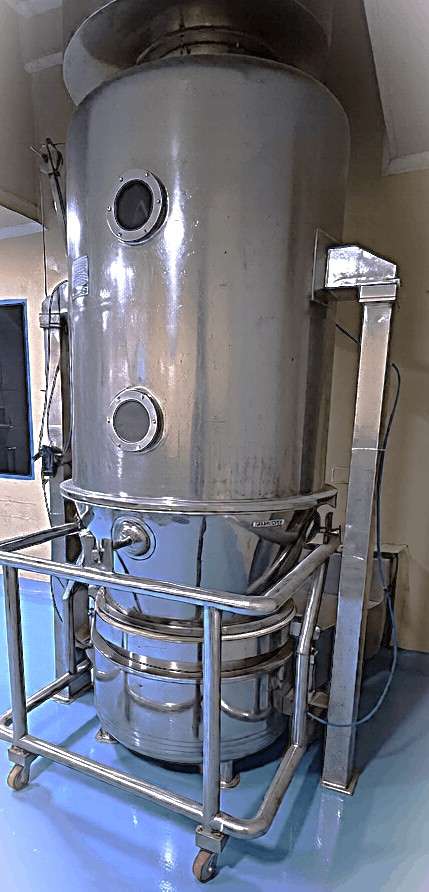
Fluid Bed Dryer is used for for drying the pharmaceutical wet granules & powder specially used in solid dosage technology.
In FBD air is allowed to flow through bed of solid powdered material in upward direction with velocity greater than setting rate of particles, the solid particles will be blown up and become suspended in the air stream.
Use of hot air to fluidizing the bed will increase the drying rate of material.
FBD contains a SS 316 Chamber having removable perforated bottom known as product container.
Air is introducing from the bottom of container and heated at required temperature by electrical heater.
Hot air is passed through filtered and then pass through the bed of the material.
This air flow is generated by the blower fitted with suitable length of ducting at the service area.
As the flow of air increase the bed known as FBD bag, expands and particles of powder starts a turbulent motion. Due to the regular contact hot air material gets dry.
Main Pillar and Expansion Chamber
Basic design of Expansion chamber is mounting on two pillars.
The pillar is made of SS 304 square tube having thickness more than 4 mm.
Pneumatic Cylinder for filter bag up/down is also mounted on the pillar.
Fluidized Bed Chamber (Expansion Housing) is made from Stainless Steel grade SS 316.
Expansion Chamber is in single piece construction.
Chamber is fully locked with inflatable seals with interlock.
Chamber will be provided with an inspection window & light window duly sealed with toughened glass.
More than 1.75 times space in litre between product container & filter bag.
Exhaust & Explosion flap connections are provided on top of chamber OR as per room layout.
Explosion vent is fixed with a thin aluminium sheet.
Provision of FBP with three level adjustment of spray nozzle if height is not concern as per room.
Read Also:- Performance Qualification of Tray Dryer
Product Container
Basic machine with 2/3 Nos Product Container with trolley will be provided.
Product Container made from SS 316.
Product container volume will be more than 360 litres.
Product batch size 100 to 120 kg depending upon the bulk density of the powder.
Sampling port is part of machine in both container.
Product temperature measurement sensor is available at product container for better process accuracy.
Perforated air distribution plate along with Dutch weave mesh will be provided with quick opening toggle clamp.
Glass window will be provided on the product container for process visualize.
Container will be on movable trolley made of SS 304 with PU castor.
Inlet Chamber
Inlet Chamber is made of Stainless Steel SS 304.
Temperature sensor for measuring of inlet air temperature.
Inlet Chamber is mounted on main pillars with an adjustable design.
Inlet Chamber will be made from 4 mm thickness.
The chamber is having water drain system with TC based connection.
Typically design air path for proper fluidization.
Special design air entry in inlet chamber for proper lifting of wet mass.
Filter Bag & Inflatable Gasket
The filter bag is made up of 20 micron PC stain cloth.
The bag filter assembly is comprised of a top ring for holding the bag and sealing ring with an inflatable gasket.
The shaking sequence is controlled by the shaking time parameters to shake off accumulated powder on the filter bag which blocks exhaust air flow however shaking disrupts fluidization in the drying chamber, therefore the system is designed with the intermittent shaking sequence.
The Following features will be provided for process requirement.
Product Temperature Set, Actual, Hi Limit, Lo Limit.
Temperature Control through PID method for precise accuracy.
Process Timing set, Actual, filter bag cleaning time, Filter bag cleaning cycles.
Speed Adjustment of blower via frequency control set, Hi Low and Actual.
Recipe Parameters, Batch code, Operator code, Product code, batch parameters.
Process Parameters like Temperature, blower Speed and Process Time.
Safety interlocks.
Process Limits and Alarms.
Recipe Handling up to 99 Recipes.
Batch Data like Operator Name , Operator Code, Product Name, Product Code,
Batch Size, Sub batch Size, Lot no, Date of Manufacturing, Expire date.
Technical Specification:
| Sr. No. | Particulars | Specification |
| AIR HANDLING UNIT | ||
| AHU Construction | Double Skin | |
| AHU Frame work | 2 mm thick aluminium Hollow Section | |
| AHU Panels | Double Skin with Insulation | |
| Insulation Thickness | 50 mm | |
| Insulation material | PUF | |
| Inner Skin Construction | From Inlet Air to Hepa Filter -Inner skin GI 24 SWG from Hepa filter (Hepa section) to Air Outlet – Inner skin ss 304 24 SWG | |
| Outer Skin of AHU | 24 SWG Powder Coated- Blue/ Green colour | |
| PAO Testing Provision | Should be as per guide line Schedule -M | |
| AHU Mounting | Skid mounting – Skid will be manufactured from Mild steel | |
| ELECTRICAL HEATER | ||
| Total KW | As per design | |
| Heater Bank | As per design | |
| Header | SS 304 | |
| PRE FILTERS | ||
| Type | HDPE 3 Ply washable with Aluminium flanged case | |
| Size | As per AHU designee | |
| Efficiency | 90% down to 10 micron | |
| Filter Frame | 16 G Aluminium Sheets | |
| MICRO VEE FILTERS | ||
| Type | HDPE 5 ply washable with Aluminium flanged case | |
| Size | As per design | |
| Efficiency | 95% down to 3 micron | |
| Filter Frame | 16 G Aluminium sheets | |
| HEPA FILTERS | ||
| Type | Glass impregnated paper with SS 304 case | |
| Size | As per design | |
| Efficiency | 99.97% down to 0.3 micron | |
| Filter Frame | 16 G SS 304 sheets | |
| EXHAUST AIR HANDLING UNIT | ||
| Exhaust AIR volume | 4500-5000 M3 /Hr | |
| Static Pressure of Fan | 750-850 mm wg @ 90 degree Celsius 580-680 mm WG @ 20 degree Celsius | |
| Type of Blower | SWSI high pressure blower | |
| Fan Construction | Spark Proof using FRP Lining | |
| Fan Speed Control | Variable Frequency drive | |
| MOC | Fan casing, Impeller, shaft inlet cones Hub etc of GI/MS Blower will be mounted on Anti Vibration Pad. | |
| CONTROL SYSTEM | ||
| Equipment Control Via | PLC | |
| PLC Make | Allen- Bradelly, Delta or Equivalent | |
| Frequency drive | Allen- Bradelly, Delta or Equivalent | |
Safety Features:
Blower Motor thermal overload.
All temperature sensor are equipped with independent safety system.
Filter Bag Up/ Down are equipped with independent sensor.
Locking Cylinder open/close are equipped with independent sensor.
Positive earthing is interlocked with system and safety.
Pressure switch for Air System.
Emergency stop on HMI.
Batch Halt
Batch Complete
List of Abbreviations.
| URS | User Requirement Specification |
| ENG | Engineering |
| QA | Quality Assurance |
| CFM | Cubic feet per minute |
| mm | Milli Meter |
| Ltr | Litre |
| Hr | Hour |
| MOC | Material of Construction |
| HMI | Human Machine Interface |
| mmWG | Milli meter of water gauge |