OBJECTIVE for DQ of Sampling Booth
To determine that the DQ of Sampling Booth (RLAF) Design Qualification perform as intended by repeatedly running the system on its intended schedules and recording all relevant information and data. Results must demonstrate that Design consistently meets per-determined specifications under normal condition, and where appropriate the worst case situations.
TABLE OF CONTENT
| Description |
| Objective |
| Table of contents |
| Scope |
| Pre-Approval of Documents |
| Responsibility (client and manufacturer) |
| Scope of supply |
| Brief process description |
| Technical specifications |
| Safety features and alarms |
| Technical specifications of the bought out components |
| Post approval of Documents |
| List of Abbreviations |
SCOPE
The scope of this qualification document is to perform the Design qualification to verify the installed components as described in DQ.
This document is applicable for Sampling Booth (Reverse Laminar Air flow).
PRE APPROVAL OF DOCUMENTS for DQ of Sampling Booth
Prepared by
| Designation | Name | Date | Signature |
| Executive/Officer QA |
Reviewed By
| Designation | Name | Date | Signature |
| Head Engineering | |||
| Head Production | |||
| Head Warehouse | |||
| Head Quality Control |
Approved by
| Designation | Name | Date | Signature |
| Head QA |
RESPONSIBILITY (Client and Manufacturer) :
Client:
To provide the Scope of supply.
To give final approval to drawing and technical data sheet.
Manufacturer:
To design, engineer and provide complete technical details of the Equipment.
To confirm safe delivery of the equipment to the user site.
To ensure that no un-authorized and/or unrecorded design modifications shall take place. If at any point of time, any change is desired by mutually agreed design, change control procedure shall be followed and documented.
SCOPE OF SUPPLY:
Design of the machine shall meet the Scope of Supply finalized with the Customer.
To define the customer’s & the manufacturer’s responsibilities.
To provide the brief process description of Sampling Booth (Reverse Laminar Air flow).
To provide the technical Specifications of the Sampling Booth (Reverse Laminar Air flow).
To provide the information on bought out components.
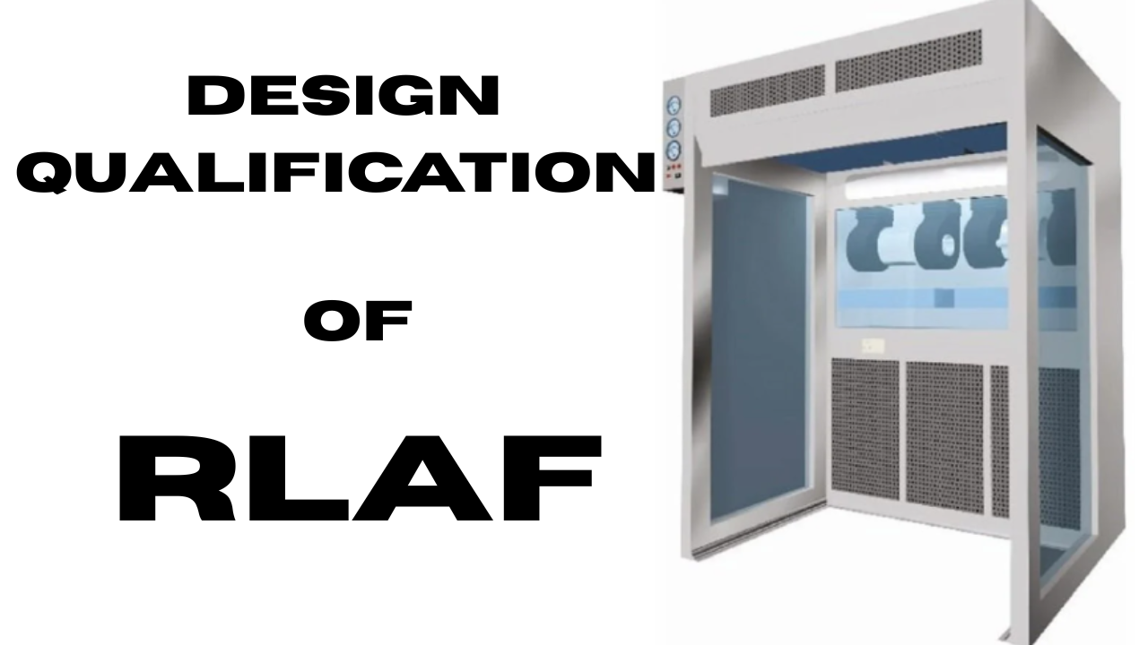
BRIEF PROCESS DESCRIPTION
Reverse Laminar Air Flow (RLAF) is a specialized air handling system used in the pharmaceutical industry to maintain a controlled and contaminant-free environment. By directing airflow from a contaminated area towards a clean area, RLAF prevents the introduction of contaminants into critical zones, ensuring the safety and quality of pharmaceutical products. Reverse Laminar Air Flow (RLAF), or Reverse Laminar Flow (RLAF), is a specialized air handling system used in pharmaceutical and clean room environments. It is designed to maintain a controlled environment by preventing the contamination of sensitive products, equipment, or processes.
Unlike traditional laminar airflow systems, where the air flows from a clean area toward a contaminated area, RLAF operates in the opposite direction. The air flows from a contaminated area towards a clean area, minimizing the risk of contaminant introduction
The working principle of Reverse Laminar Air Flow (RLAF) involves the controlled direction of airflow from a contaminated area towards a clean area, ensuring that contaminants are contained and prevented from reaching critical zones. Here’s a breakdown of the working principle:
- Airflow Direction: In RLAF, the airflow is reversed compared to traditional laminar flow systems. Instead of flowing from a clean area toward a contaminated area, the air is directed from a contaminated area toward a clean area.
- Contaminated Area: The contaminated area refers to the region where potentially harmful substances, particles, or processes are present. This can include areas with active pharmaceutical ingredient (API) handling, equipment cleaning, or other processes that generate contaminants.
- Clean Area: The clean area is the designated zone where sensitive pharmaceutical products, equipment, or processes requiring a controlled environment are located. It could be an aseptic filling line, sterile compounding area, or any other critical zone.
- Airflow Pattern: RLAF creates a controlled airflow pattern that effectively prevents contaminants from entering the clean area. The airflow is typically generated by ventilation systems, air handlers, and HEPA (High-Efficiency Particulate Air) filters.
- Containment and Exhaust: The RLAF system ensures that the contaminated air is contained within the contaminated area and exhausts safely. This prevents the spread of contaminants to the clean area and maintains the required cleanliness levels.
- Air Filtration: RLAF systems incorporate HEPA filters that effectively capture and remove airborne particles and microorganisms. These filters have high efficiency in removing particulate matter, typically with an efficiency of 99.97% for particles as small as 0.3 micrometers.
- Validation and Monitoring: Regular validation and monitoring of the RLAF system are crucial to ensuring its effectiveness. Airflow velocity measurements, particle counts, and microbial sampling are performed to verify that the system is operating within specified parameters and meeting regulatory standards.
- The basic construction of the machine consists of :
- Standard stainless steel 304 with matt finish
- Non metallic contact parts, any material with food grade quality having no potential impact on the products.
Body:
The body of the RLAF consists of the outer casing and the inner chamber.
UV Light
UV light are designed inside RLAF for disinfection of material.
Fan
It sucks the air and blows it through HEPA filter. The clean air will go into the chamber to sterilize the objects
Filters
Filters are used to remove the airborne particles
Differential pressure gauge
To check the differential pressure across HEPA filters
Blower and fan
Clean air enters the inner space of RLAF, dilutes and filters the air inside.
Electrical chamber and mechanical chamber:
All mechanical components such as gears, motors, as well as electrical components such as wiring, switches, and MCBs, are installed in this segment.
TECHNICAL SPECIFICATION for DQ of Sampling Booth:
| Sr. No. | Particulars | Specification |
| 1 | Make | As per Requirement |
| 2 | Model | GMP |
| BODY | ||
| 1 | Overall size | 1330x1565x 2130mm |
| 2 | Internal Size | 1220x915x1830mm |
| 3 | Cabinet MOC | SS 304 |
| 4 | PAO Port | SS 304 |
| MAGNEHELIC GAUGE | ||
| 1 | Make | As per Requirement |
| 2 | Qty | 1 Nos |
| 3 | Range | 0-50 mmwc |
| MAGNEHELIC GAUGE | ||
| 1 | Make | As per Requirement |
| 2 | Qty | 1 Nos |
| 3 | Range | 0-25 mm wc |
| Mini Pleat HEPA Filter | ||
| 1 | Make | As per Requirement |
| 2 | Type & Size | Box Type &1220x 610x 69mm |
| 3 | Efficiency | 99.997% @ 0.3 Micron |
| 4 | Rated Capacity | 750 CFM |
| 5 | Media | Fiber Glass |
| 6 | Frame | Aluminum |
| 7 | Qty. | 01 Nos |
| Pre -Filter | ||
| 1 | Make | As per Requirement |
| 2 | Type & Size | Flange Type &790x 560 x 50 mm |
| 3 | Efficiency | 90% down to 10Micron |
| 4 | Frame | Aluminum |
| 5 | QTY. | 02 Nos. |
| Mini Pleat HEPA Filter | ||
| 1 | Make | As per Requirement |
| 2 | Type & Size | Box Type & 610x 305x 69mm |
| 3 | Efficiency | 99.997% @ 0.3 Micron |
| 4 | Rated Capacity | 480 CFM |
| 5 | Media | Fiber Glass |
| 6 | Frame | Aluminum |
| 7 | Qty. | 02 Nos |
| Blower Motor Drive Unit | ||
| 1 | Make | As per Requirement |
| 2 | Hp/rpm | 1/2 1350 rpm |
| 3 | Watt/Phase | 230 Watt, 1 Phase |
| 4 | Qty. | 02 No. |
| Suction Grill | ||
| 1 | Make | As per Requirement |
| 2 | Type | Capsule Type Perforated |
| LED Light | ||
| 1 | Make | As per Requirement |
| 2 | Size | 4 Feet |
| 3 | Watt | 20w |
| 4 | Qty. | 1 Nos |
| Switch | ||
| 1 | Make | As per Requirement |
| 2 | Watt | 10 AMP. |
| 3 | Qty. | 3 Nos. |
| 4 | Power Supply | Single Phase 230 Volt |
| 5 | Type | On-Off |
| MCB | ||
| 1 | Make | As per Requirement |
| 2 | Watt | 16 AMP |
| 3 | Qty. | 1 Nos |
| UV Light | ||
| 1 | Make | As per Requirement |
| 2 | Size | 1 Feet |
| 3 | Watt | 8w |
| 4 | Qty. | 1 Nos |
| Hour Meter | ||
| 1 | Make | As per Requirement |
| 2 | Qty. | 1 Nos |
SAFETY FEATURE & ALARM
| Safety feature | Function |
| Electrical Insulation | Safety |
| Earthing | To avoid the shock |
TECHNICAL SPECIFICATION OF THE BOUGHT OUT COMPONENT
A) Instruments Requiring Calibration
| Sr. No. | Instrument | Location | Make | SR. NO. |
| 1 | Magnehelic gauge | Sampling Booth | ||
| 2 | Magnehelic gauge | Sampling Booth |
B) Equipment structure:
| Sr. No | Description | Specified | Location |
| 1 | Make. | Sampling Booth | |
| 2 | Serial No. | Sampling Booth |
POST APPROVAL OF DOCUMENTS
Prepared by
| Designation | Name | Date | Signature |
| Executive/Officer Engineering |
Reviewed By
| Designation | Name | Date | Signature |
| Head Engineering | |||
| Head Production | |||
| Head Warehouse | |||
| Head Quality Control |
Approved by
| Designation | Name | Date | Signature |
| Head QA |
LIST OF ABBREVIATIONS
| ENG | Engineering |
| DQ | Design Qualification |
| RLAF | Reverse Laminar Air Flow |
| HEPA | High Efficiency Particulate Air |
| UV | Ultra violet |
| MCB | Miniature Circuit Breaker |
| GMP | Good manufacturing Practices |
| mm | Millimetre |
| MOC | Material of construction |
| CFM | Cubic Feet Per Minute |
| LED | Light Emitting Diode |
| Amp. | Ampere |