Objective of IQ for Dynamic Pass Box
To determine that the IQ for Dynamic Pass Box perform as intended by repeatedly running the system on its intended schedules and recording all relevant information and data. Results must demonstrate that installation consistently meets per-determined specifications under normal condition, and where appropriate the worst-case situations.
Table of Content
| PARTICULARS | PAGE NO. |
| TITLE PAGE | |
| TABLE OF CONTENT | |
| OBJECTIVE | |
| SCOPE | |
| PRE APPROVAL OF DOCUMENTS | |
| SCOPE OF SUPPLY | |
| BRIEF PROCESS DESCRIPTION | |
| TECHNICAL SPECIFICATION | |
| TECHNICAL SPECIFICATION OF THE COMPONENTS | |
| REQUIRED UTILITIES | |
| INSTALLATION QUALIFICATION PROCEDURE | |
| SAFETY FEATURES & ALARAM | |
| POST APPROVAL OF DOCUMENTS | |
| LIST OF ABBREVIATIONS |
SCOPE
The scope of this qualification document is to perform the installation qualification to verify the installed components as described in IQ.
This document is applicable for Dynamic pass box located at factory premises.
PRE APPROVAL OF DOCUMENTS
Prepared by
| Designation | Name | Date | Signature |
| Executive/Officer Engineering |
Reviewed By
| Designation | Name | Date | Signature |
| Head Engineering | |||
| Head Quality Control | |||
| Head Warehouse | |||
| Head Production |
Approved by
| Designation | Name | Date | Signature |
| Head QA |
SCOPE OF SUPPLY:
| Description | Specification |
| Make | |
| Model/Serial No. | As per cGMP model/ 420/01/25 |
| Control system | 230volts, Single phase power supply |
BRIEF PROCESS DESCRIPTION:
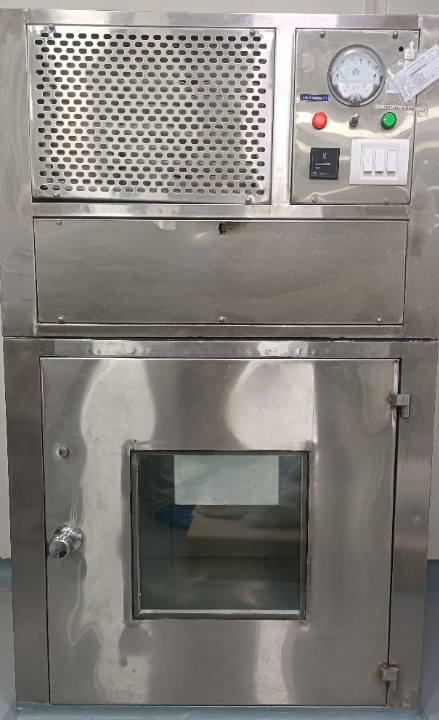
Dynamic pass box is normally used to transfer materials and goods between clean rooms of different levels or between clean room and non-clean room. Besides UV light and an interlock system, dynamic pass box is equipped with a suction HEPA filter. A dynamic pass box works like an airlock or laminar it has an interlocking system on both sides to protect from contamination and cross-contamination. Dynamic pass box door can open one side at once, and the other side door remains closed.
Dynamic pass box is a self-cleaning pass box. The air sucked by a centrifugal blower than passed through HEPA filter. After the pressure is equalized, the filtered air enters the working zone at a uniform air velocity, forming a clean working environment
When the material is put inside pass box & the door is closed, UV light will turn on and material is placed under UV for some time to kill bacteria. Then the material can be taken out
TECHNICAL SPECIFICATION:
| Particulars | Specification | Identified by / Sign. & date | Remarks |
| Make | |||
| Model | As per cGMP model | ||
| Capacity | ISO Class5 (ISO 14644-1:1999(E))/Class 100(U.S FED STD. 209E) | ||
| Overall dimension (mm) | 1040(W) X 1020(D) X 1200 (H) | ||
| Workingdimension (mm) | 800(W)X800(D)X800(H) | ||
| Pass box type | 3-way opening | ||
| General components | Main Cabinet HEPA Filter Pre FilterFresh Air Filter Motor Blower Magnehelic Gauge Atmospheric Nozzle PAO Port Electromagnetic Interlocking Controller with OLED Display LED Light with Protective Grill UV Light with Protective Grill Power Supply Plug Permanent Magnet | ||
| Identification | DetailsofMake,Name,Serial.No.,Capacity,ModelandYearofmanufactureshouldbeavailable | ||
| Utility Requirement | 230 V ac, 1 Ph. 50/60Hz. |
TECHNICAL SPECIFICATION OF THE BOUGHT-OUT COMPONENT
| Particulars | Specification | Identified by / Sign. & date | Remarks |
| Make | |||
| Unit Serial No. | |||
| Pre Filter | Qty – 1 nos. Size – 810 x 260 x 50 mm Make – Rating – EU-4 Efficiency – 90% down to 5 µ MOC of frame – Aluminum Type (Flange/Box) – Flange type Grill Provision – No | ||
| HEPA filter | Qty – 1 nos. Size – 610 x 610 x 69 mm Make – Rating – EU-14 Efficiency – 99.997% down to 0.3 µ MOC of frame – Aluminum Extrusion Type (Flange/Box) – Mini Pleat HEPA filter Box type Grill Provision – No | ||
| Fresh Filter | Qty – 1 nos. Size – 200 x 200 x 50 mm Make – Rating – EU-4 Efficiency – 90% down to 5 µ MOC of frame – Aluminum Type (Flange/Box) – Box type | ||
| Motor Blower | Qty – 1 nos. Make – Rated power – 300 W Rated RPM – 2050 Phase (1φ/3φ) – Single phase (1φ) | ||
| Magnehelic gauge | Qty – 1 nos. Type – Magnehelic gauge Make – Range – 0 to 50 mm of WC | ||
| UV light | Qty – 01 nos. Size – 1.5 ft. Watt – 15 W | ||
| LED Light | Qty – 02 nos. Size – 2 ft. Watt – 10 W | ||
| On/Off Switches | Qty – 02 nos. Use – For Blower, UV Light & LED Light | ||
| Upstream Port | Qty – 01 nos. Use – For PAO Testing Upstream of HEPA filter | ||
| Other details | Electromagnetic Card 3 Door DPB – Harrison Power Adaptor(12VDC) – 1 Nos. Buzzer – 1 Nos. MCB DP(6 AMP) – 1 Nos. Contactor (9 AMP) – 1 Nos. Regulator (450W) – 1 Nos. Connector – Phoenix Atmospheric Nozzle – 1 Nos. Material of Construction – SS 304 PVC Tube for Magnehelic Gauge – 2 Mtr. Supply Cable – 3 Mtr. As Built Drawing No. – MSPL/ACC/DPB/199 Electrical Circuit Diagram. – MSPL/ACC/ELEC/199 |
REQUIRED UTILITES:
| Utility/ Parameter | Features |
| Electrical Utility | Voltage: 220VAC ± 5% |
| Frequency: 50 Hz ± 2% | |
| Connection: 3 Wire | |
| Phase: 1 Phase, 1 Neutral,1Earthing |
PROCEDURE of IQ for Dynamic Pass Box :
- The location and placement of machine shall be verified.
- The installation site has been checked for meeting the installation requirements.
- All the equipment of the system has been identified and verified.
- The availability of purchase documents has been verified and recorded.
- The availability of GA drawings/Operational manual has been checked.
Procedure
- Remove the components of Dynamic Pass Box from its packing only prior to installation of equipment. To avoid the scratches and breakages, it is advisable to remove the final wrapping just before entering the controlled Environment area.
- Perform a general physical inspection to make sure that no shipping damage has occurred.
- Choose a suitable location where the Dynamic Pass Box can be placed.
- Dynamic Pass Box comprises of HEPA filters, Fresh Air Filter, Pre Filters and Motor Blower supply plenum. Assemble all components as shown in the drawings. HEPA filters should be the last component to be assembled. Direction of air flow is important and while clamping down the filter it is important to ensure that all bolts are tightened.
- After mounting the Motor Blower with the help of Nut & Bolt, try rotating the impellers
- manually to ensure free rotation of impeller.
- Manually site the cabinet at the chosen location and connect the power cord. Remove the protective surface coverings of the cabinet.
- Wipe down the interior and exterior of the Cabinet with water or mild household detergent.
- Before Switching the Unit to “ON “position adjusts the zero in Differential Pressure Gauge.
- Power ON the Cabinet and observe normal Motor Blower & Light Operation.
- Unless and otherwise specified the units are designed to deliver air in the Dynamic Pass Box regime (90 FPM with a uniformity of ± 20 %) at a pressure drop of 7 to 15 mm of WC.
SAFETY FEATURE & ALARM
| Safety feature | Function | Identified by/ Sign. & date |
| Electrical Insulation | Safety | |
| Earthing | To avoid the shock |
POST APPROVAL OF DOCUMENTS
Prepared by
| Designation | Name | Date | Signature |
| Executive/Officer Engineering |
Reviewed By
| Designation | Name | Date | Signature |
| Head Engineering | |||
| Head Quality Control | |||
| Head Warehouse | |||
| Head Production |
Approved by
| Designation | Name | Date | Signature |
| Head QA |
LIST OF ABBREVIATIONS
| IQ | Installation Qualification |
| DPB | Dynamic Pass box |
| WH | Warehouse |
| QA | Quality Assurance |
| URS | User Required Specification |
| UV | Ultra Violet |
| HEPA | High Efficiency Particulate Air |
| SS | Stainless Steel |
| MCB | Miniature Circuit Board |
| ISO | Indian Standardized Organisation |
| cGMP | Current Manufacturing practices |
| MM | Millimetre |
| PAO | Poly Alpha Olefin |
| OLED | Organic Light Emitting Diode |
| V | Voltage |
| AC | Alternate Current |
| MOC | Material of construction |
| µ | Micron |
| RPM | Revolution per minute |
| WC | Water Column |
| W | Watt |
| Amp. | Ampere |