Objective of IQ for Sampling Booth
To determine that the IQ for Sampling Booth (Reverse Laminar Air flow) perform as intended by repeatedly running the system on its intended schedules and recording all relevant information and data. Results must demonstrate that installation consistently meets per-determined specifications under normal condition, and where appropriate the worst case situations.
Table of Content
| PARTICULARS | PAGE NO. |
| Title page | |
| Table of contents | |
| Objective | |
| Scope | |
| Pre approval of documents | |
| Scope of supply | |
| Brief process description | |
| Required utilities | |
| Installation qualification procedure | |
| Safety features & alarm | |
| Technical specification | |
| Technical specification of the components | |
| Post approval of documents | |
| List of abbreviations |
Scope
The scope of this qualification document is to perform the installation qualification to verify the installed components as described in IQ.
This document is applicable for Sampling Booth (Reverse Laminar Air flow) located at company.
Pre Approval Of Documents
Prepared by
| Designation | Name | Date | Signature |
| Executive/Officer Engineering |
Reviewed By
| Designation | Name | Date | Signature |
| Head Engineering | |||
| Head Production | |||
| Head Warehouse | |||
| Head Quality Control |
Approved by
| Designation | Name | Date | Signature |
| Head QA |
SCOPE OF SUPPLY:
| Description | Specification |
| Make | |
| Model | GMP |
| Serial no | |
| Control system | 220 volts, Single phase power supply |
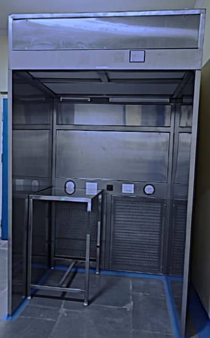
Brief Process Description of IQ for Sampling Booth
Reverse Laminar Air Flow (RLAF) is a specialized air handling system used in the pharmaceutical industry to maintain a controlled and contaminant-free environment. By directing airflow from a contaminated area towards a clean area, RLAF prevents the introduction of contaminants into critical zones, ensuring the safety and quality of pharmaceutical products. Reverse Laminar Air Flow (RLAF), or Reverse Laminar Flow (RLAF), is a specialized air handling system used in pharmaceutical and clean room environments. It is designed to maintain a controlled environment by preventing the contamination of sensitive products, equipment, or processes.
Unlike traditional laminar airflow systems, where the air flows from a clean area toward a contaminated area, RLAF operates in the opposite direction. The air flows from a contaminated area towards a clean area, minimizing the risk of contaminant introduction
The working principle of Reverse Laminar Air Flow (RLAF) involves the controlled direction of airflow from a contaminated area towards a clean area, ensuring that contaminants are contained and prevented from reaching critical zones. Here’s a breakdown of the working principle:
Airflow Direction: In RLAF, the airflow is reversed compared to traditional laminar flow systems. Instead of flowing from a clean area toward a contaminated area, the air is directed from a contaminated area toward a clean area.
Contaminated Area: The contaminated area refers to the region where potentially harmful substances, particles, or processes are present. This can include areas with active pharmaceutical ingredient (API) handling, equipment cleaning, or other processes that generate contaminants.
Clean Area: The clean area is the designated zone where sensitive pharmaceutical products, equipment, or processes requiring a controlled environment are located. It could be an aseptic filling line, sterile compounding area, or any other critical zone.
Airflow Pattern: RLAF creates a controlled airflow pattern that effectively prevents contaminants from entering the clean area. The airflow is typically generated by ventilation systems, air handlers, and HEPA (High-Efficiency Particulate Air) filters.
Containment and Exhaust: The RLAF system ensures that the contaminated air is contained within the contaminated area and exhausts safely. This prevents the spread of contaminants to the clean area and maintains the required cleanliness levels.
Air Filtration: RLAF systems incorporate HEPA filters that effectively capture and remove airborne particles and microorganisms. These filters have high efficiency in removing particulate matter, typically with an efficiency of 99.97% for particles as small as 0.3 micrometres.
Validation and Monitoring: Regular validation and monitoring of the RLAF system are crucial to ensuring its effectiveness. Airflow velocity measurements, particle counts, and microbial sampling are performed to verify that the system is operating within specified parameters and meeting regulatory standards.
Required Utilities:
| Sr. No. | Utility/ Parameter | Features |
| 1 | Electrical Utility | Voltage: 220 VAC ± 5% |
| 2 | Frequency: 50 Hz ± 2% | |
| 3 | Connection: 3 Wire | |
| 4 | Phase: 1 Phase, 1 Neutral,1Earthing |
Installation qualification procedure:
The location and placement of machine shall be verified.
The installation site has been checked for meeting the installation requirements.
All the equipment of the system has been identified and verified.
The availability of purchase documents has been verified and recorded.
Physical verification:
| Parameters | Acceptance Criteria | Observation (OK/NOT OK) | Done by |
| Horizontal levelling of the equipment | Should be perfectly horizontal | ||
| Positioning of the equipment | It should be aligned Vertically straight. There should be enough space for maintenance purposes. | ||
| Floor balancing | It should not give any vibration at any corner of the equipment and should be well placed on the floor | ||
| Identification plate | Name of the equipment and/or suppliers name to be available on the equipment | ||
| Surface finish of equipment | Should be smooth and Glossy. | ||
| Any physical damage to the equipment / floor or Room walls and door. | No physical scratches or damage should be observed |
Safety Feature & Alarm
| Safety feature | Function | Identified by/Date |
| Electrical Insulation | Safety | |
| Earthing | To avoid the shock |
Technical specification for IQ for Sampling Booth:
| Parameter | Specification | Actual | Sign/Date | Remark |
| Make | ||||
| Model | GMP | |||
| Overall size | 1330x1565x 2130mm | |||
| Internal Size | 1220x915x1830 mm | |||
| Make | ||||
| Qty | 1 Nos | |||
| Range | 0-50 mmwc | |||
| Make | ||||
| Qty | 1 Nos | |||
| Range | 0-25 mm wc | |||
| Make | ||||
| Type & Size | Box Type &1220x 610x 69mm | |||
| Efficiency | 99.997% @ 0.3 Micron | |||
| Rated Capacity | 750 CFM | |||
| Media | Fiber Glass | |||
| Frame | Aluminum | |||
| Qty. | 01 Nos | |||
| Make | ||||
| Type & Size | Flange Type &790x 560 x 50 mm | |||
| Efficiency | 90% down to 10Micron | |||
| Frame | Aluminum | |||
| QTY. | 02 Nos. | |||
| Make | ||||
| Type & Size | Box Type & 610x 305x 69mm | |||
| Efficiency | 99.997% @ 0.3 Micron | |||
| Rated Capacity | 480 CFM | |||
| Media | Fiber Glass | |||
| Frame | Aluminum | |||
| Qty. | 02 Nos | |||
| Make | ||||
| Hp/rpm | ½ 1350 rpm | |||
| Watt/Phase | 230 Watt, 1 Phase | |||
| Qty. | 02 No. | |||
| Make | ONS Industrial Solutions | |||
| Type | Capsule Type Perforated | |||
| Make | ||||
| Size | 4 Feet | |||
| Watt | 20w | |||
| Qty. | 1 Nos | |||
| Make | ||||
| Watt | 10 AMP. | |||
| Qty. | 3 Nos. | |||
| Power Supply | Single Phase 230 Volt | |||
| Type | On-Off | |||
| Make | ||||
| Watt | 16 AMP | |||
| Qty. | 1 Nos | |||
| Make | ||||
| Size | 1 Feet | |||
| Watt | 8w | |||
| Qty. | 1 Nos | |||
| Make | ||||
| Qty. | 1 Nos |
Technical Specification of The Component
Instruments Requiring Calibration
| Sr. No. | Instrument | Location | Make | SR. NO. |
| 1 | Magnehelic gauge | Sampling Booth | ||
| 2 | Magnehelic gauge | Sampling Booth |
Equipment structure:
| Sr. No | Description | Specified | Location |
| 1 | Make. | Sampling Booth | |
| 2 | Serial No. | Sampling Booth |
Post Approval of Documents
Prepared by
| Designation | Name | Date | Signature |
| Executive/Officer Engineering |
Reviewed By
| Designation | Name | Date | Signature |
| Head Engineering | |||
| Head Production | |||
| Head Warehouse | |||
| Head Quality Control |
Approved by
| Designation | Name | Date | Signature |
| Head QA |
List of Abbreviations
| ENG | Engineering |
| IQ | Installation Qualification |
| RLAF | Reverse Laminar Air Flow |
| HEPA | High Efficiency Particulate Air |
| UV | Ultra violet |
| MCB | Miniature Circuit Breaker |
| GMP | Good manufacturing Practices |
| mm | Millimetre |
| MOC | Material of construction |
| PAO | Poly alpha olefin |
| CFM | Cubic Feet Per Minute |
| LED | Light Emitting Diode |
| Amp. | Ampere |
| WC | Water Content |